
Yesterday I watched a trailer for the new James Bond movie – “No time to die” and I loved the animation at the end, so I decided to recreate it with web technologies.
In this part one I will show you how to reproduce this kind of SVG shapes.
Let’s go!
Assumptions
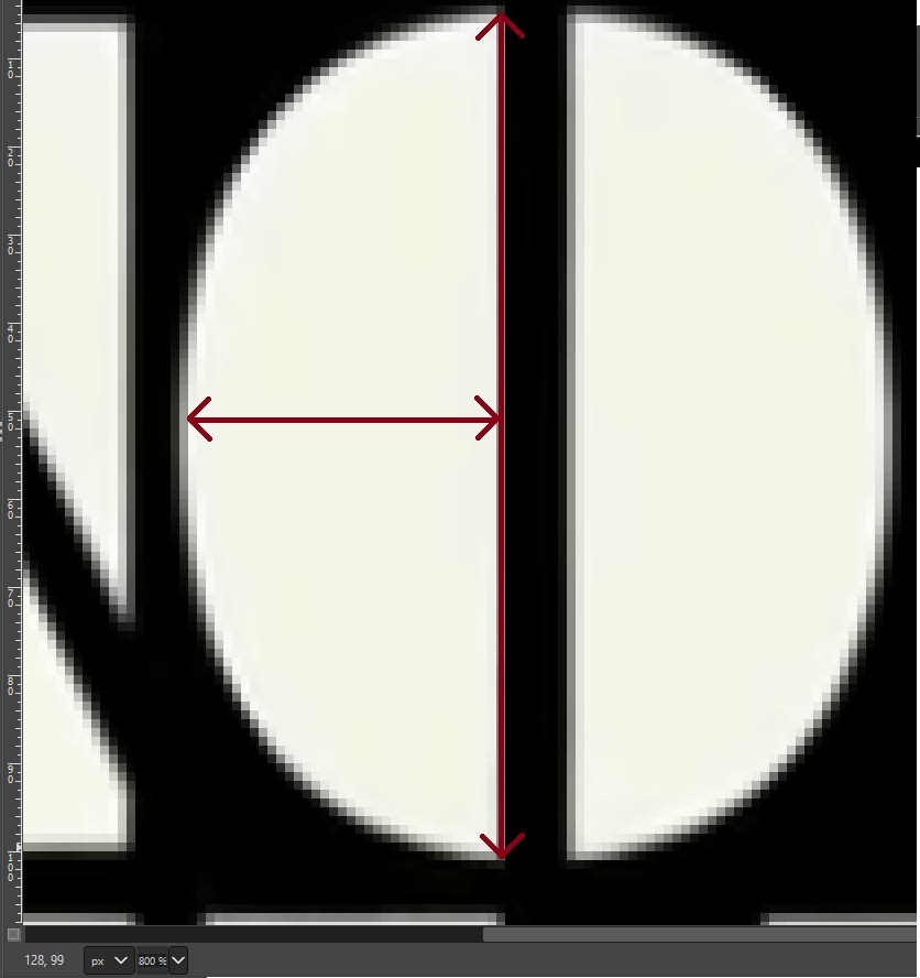
Original image we’ll reproduce:
Technology: SVG
Drawing shapes
There are ten shapes in the image we will need to code. That’s less than there are shapes in the image, but notice, that for the letter “O” we need to know only one half, because we can duplicate and mirror this first half to get the second half.
The cleaner the SVG, the smoother animation process goes, so I decided to hand code all the shapes. They look fairly simple to me.
Hand-coding SVG
It may sound scary, but it’s not. We’ll start with the simplest shape we can – the rectangle (letter “I”).
Our empty SVG looks like this:
<svg width="1000" height="1000" viewbox="-5 -5 1000 1000">
  <path d=""></path>
</svg>
It has an arbitrary width and height of 1000px, so that we have enough space to draw and one path element inside it.
The viewbox value is now set to -5 -5 1000 1000, which translates into “I want the visible area to start at point with coordinates -5 (first number), -5 (second number), have 1000 width (third number) and 1000 height (fourth number)”. Note that this numbers have no units and that third and fourth numbers are not coordinates of right bottom corner, but width and height. Usually SVGs start at 0,0, but I want to make my shapes start at 0,0 and still have some room to breathe on top and left.
Now let’s fill this path’s d attribute.
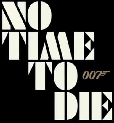
We open the image in a any program, that will let us zoom in and get the coordinates of top left corner of letter “I” (I used GIMP). In this case it’s 96 (x-axis) and 108 (y-axis). Note that it’s not the last light pixel in the area. Those greyish colors further to the left are there because of anti-aliasing, but if we used their coordinates our resulting image would be bigger than the original.
The same way we get the coordinates of other corners (going clockwise):
- top right
(128, 108) - bottom right
(128, 200) - bottom left
(96, 200)
Now we can code our rectangle. I prefer relative coordinates, so the path will go like this (starting in left top corner an going clockwise):
<path d="M0,0 h32 v92 v-32 z"></path>It starts at (0,0), than goes horizontally for 32 units (h32), then goes vertically for 92 units (v92), then goes horizontally for -32 units (h-32) and goes back to the first point (z).
We get value of 32 by subtracting x-coordinates of top left and top right corners and value of 92 by subtracting y-coordinates of top left and bottom left corners.
Any time the coordinates are greater than 0 current point moves to the right and to the bottom, and when coordinates are less than 0 current point moves to the left and to the top.
Closing path with z command creates line joining current point and starting point (indicated by M command).
Now we have one shape. Only nine more to go!
Polygons
Next few shapes will be polygons, which means the lines will go horizontally, vertically or diagonally, but always will be lines and not curves.
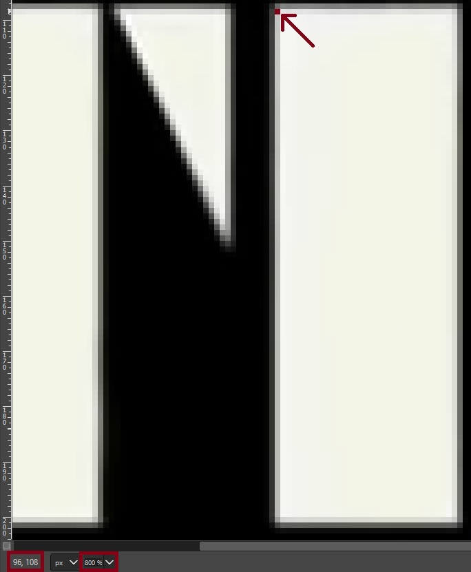
The strategy stays the same. We read the coordinates and assemble path commands. For the triangle making left part of letter “T” it goes like this:
- top left
(8,108) - top right
(27,108) - bottom left
(8,148)
This translates into a path (starting in left top corner):
<path d="M0,0 h19 l-19,40 z"></path>But I don’t really like it. In truth it is perfectly fine, but if I code it by hand anyway I can refactor it to the form I like more (without diagonal lines):
<path d="M0,0 m0,40 v40 h19 z"></path>This translates into: start at point (0,0), then go to point, that’s 0 units to the left and 40 units to the bottom WITHOUT DRAWING ANYTHING, then draw a vertical line from current point to the point 40 units above, then draw horizontal line with length of 19 units and go back to point, where vertical line begins (the last point indicated by m command).
Side note: z goes back to the last point indicated by M, m, z or Z.
Why bother with M and m if I could just write M0,40? Well, both ways the resulting SVG will look the same and M0,40 version will be a little shorter. I just like starting at 0,0 (top left corner), because it makes creating bigger compositions easier. At least for me.
Let’s move to a little more exciting shape – first part of letter “M”:
- top corner
(150,144) - middle right corner
(163,193) - bottom right corner
(161,200) - bottom left corner
(136,200)
It all translates into a path (starting at bottom left corner and going anticlockwise):
<path d="M0,0 m92 h25 l2,-7 -13,-49 z"></path>or
<path d="M0,92 h25 l2,-7 -13,-49 z"></path>or (going clockwise)
<path d="M0,92 l14,-56 13,49 -2,7z"></path>In case you’re asking where does 92 come from – it’s letter’s height we calculated while coding the letter “I”.
In most cases it doesn’t matter if we go clockwise or anticlockwise, the result on the screen is the same, so we choose the most convenient option.
Curves
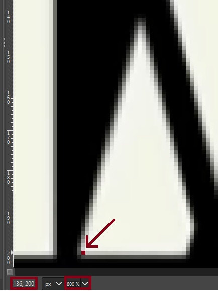
Drawing curves by reading coordinates isn’t that easy, but, we will assemble what we know already to get the best we can from letter “O”:
We can read the width and height of the shape and try to guess coordinates of control points:
<path d="M0,0 m36,92 c-36,0 -36,-92 0,-92 z"></path>This translates into: go to the right bottom corner and draw a curve with two control points. First control point is 36 units to the right from current point and 0 to to the top, the second control point is 36 units to the right from current point and 92 units to to the top. Finish the curve in point 0 units to the left from current point ant 92 units to the top from the current point.
A this point we have definitions of all of the paths we need to assemble letters and create the title of the movie. Hurray!
Paths as code:
<svg width="1000" height="100" viewBox="-5 -5 1000 100">
    <path id="n-one" d="M0,0m0,26v66h26v-11z"></path>
    <path id="n-two" d="M0,0m0,6v-6h36l41,86v6h-36z"></path>
    <path id="o-one" d="M100,0m36,92c-36,0,-36,-92,0,-92z"></path>
    <path id="t-one" d="M150,0m0,41v-41h19z"></path>
    <path id="t-two" d="M200,0h32v92h-32z"></path>
    <path id="m-one" d="M250,0m0,92h25l2,-6,-13,-51z"></path>
    <path id="m-two" d="M250,0m40,92h30l-24,-92h-20l-5,17z"></path>
    <path id="e-one" d="M300,0m35,0h30v33z"></path>
    <path id="e-two" d="M300,0m54,26v36l-19,-18z"></path>
    <path id="e-three" d="M300,0m35,92h31v-40z"></path>
</svg>
and rendered in browser:
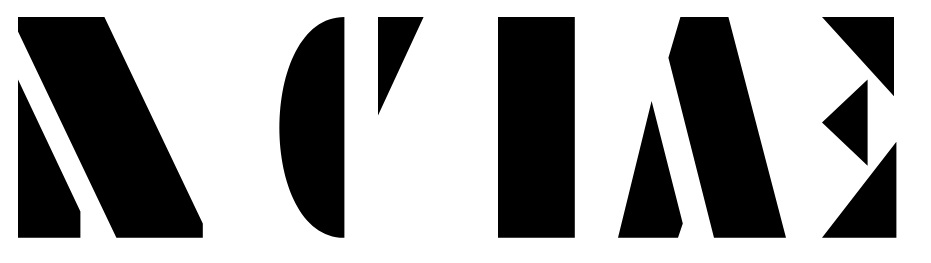
They may not look impressive yet, but in next part we’ll assemble them to letters and words. Stay tuned!